Construction Details |
|||
|
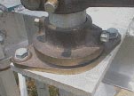
SEECO phase-over-phase GOABS� switches are designed for maintenance-free operation in severe environmental and operating conditions. The switch components are heavy-duty and rugged in their design, yet the operating effort to open and close the switch is minimal, even at higher voltages; no slamming is ever required. For ultimate reliability, SEECO phase-over-phase switches utilize a unique construction of the current carrying components and an over-toggle adjustment (figure 1) in the control mechanism. This combination of design features and adjustment procedure insures that the switch stays closed under adverse conditions, such as excessive pole deflection, vibration, and galloping conductors, without the use of blade locks or other latching devices. For the harsh, unforgiving conditions in transmission operating environments, it is the most reliable switch available. It is a proven design validated by over 40 years of successful performance. General The switch is directly connected to the operating mechanism through the rotating insulators, inter-phase pipe, lever arms, and crank arms (figure 2), and is in positive control throughout the complete opening and closing operation. The control mechanism is designed for efficient transmission of the operating force to the rotating insulator so that opening and closing of the switch can be effected in a smooth, continuous motion with minimal operating effort. Blade-Clip Assembly (Jaw) Engagement The clip assemblies are held open (figure 3) at approximately 40 degrees by a clutch and double spring arrangement housed inside the base of the clip assembly. When the blades swing closed, they engage the contact fingers, pulling the clip assemblies into the final, closed position. This simultaneous blade-clip assembly motion enables high-pressure, large contact deflection to be achieved with minimum operating effort and provides efficient leverage for breaking ice. Proper alignment of the blade with the clip assembly (jaw) contact fingers is easily accomplished with the rocker bottom feature (figure 4) of the blade-hinge assembly. This feature insures that the blade-end engages the contact fingers in the vertical center of the clip assembly. Compensation for insulator tolerances is accomplished, without using shims, by loosening and tightening two of the four bolts attaching the blade hinge assembly to the insulators. The two bolts that align parallel with the long axis of the blade are used for this adjustment, while the other two bolts are used solely to secure the rocker bottom to the insulator cap. Contact Fingers (Jaw) High-pressure, self-wiping, silver-to-copper contacts give superior conductivity without contact abrasion and provide ample mechanical and electrical security to meet industry standard high-current test requirements. The four contact fingers (figure 5) are hard-drawn copper with silver button-contacts. Large contact deflection is provided by separate fatigue-resistant backup springs to maintain high contact pressure under the extreme conditions of outdoor service. The main current path is through the hard-drawn copper fingers, not through the backup springs. The in-line arrangement (figure 6) of the contact fingers relative to the blade provides increased contact forces when the switch is subjected to high-current surges. Each contact finger and backup spring is attached to the jaw-hinge casting with two bolts, which provides a means for accurately setting contact pressure in assembly. Blade Assembly Main Bearing Assemblies On switches with 3-inch bolt circle insulators (ratings 15-69 kV), the bearings are assembled in high-strength aluminum housings (figure 8). The bearing housings for 5-inch bolt circle switches (ratings 115-161 kV) are of galvanized steel (figure 9). The 5-inch bolt circle bearings include four leveling screws to facilitate insulator alignment after assembly onto the switch. Structural Aluminum Frames Frames for switches rated 15 – 69 kV are of one-piece construction, requiring no field assembly. Frames for switches rated 115 kV and up consist of three main assemblies, which are match-marked after factory assembly and shipped disassembled for convenience in shipping and handling. Control Mechanism
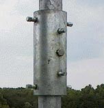
Outboard bearing assemblies (figure 10), which support the vertical pipe column, are of a greaseless, maintenance-free design and employ stainless steel ball bearings. The number of outboard bearings supplied for each vertical pipe column is based on the run length and weight of unsupported pipe. At least one outboard bearing will be supplied per column, and two may be supplied as the application warrants.
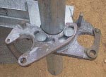
Cranks, clevises, and levers (figure 11) are heavy-duty castings of high-strength bronze. For maximum mechanical strength and durability, each component has a large material cross-section and many incorporate additional ribbing and enlarged embosses. Hardware (carriage bolts, washers, hex nuts, etc) is structural-grade galvanized steel.
Pipe couplers (figure 12) are manufactured from thick wall mechanical steel tube rather than thin wall pipe sleeves used by other manufacturers. Combined with self-piercing set screws, they insure that pipe connections are secure and that switch phases cannot slip out of synchronization.
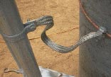
Adjustable control rod guides are furnished between the bottom phase and the locking assembly. The control rod guides and locking assembly are slotted for quick, easy alignment with the vertical control rod. The locking assembly (figure 13) is stamped with “open” and “closed” position markings and has provisions for padlocking in either position. The individual lock segments are heavy-duty castings of high-strength bronze, and are slotted for easy adjustment and alignment. A galvanized steel mounting bracket and hardware are also part of this assembly. Ground strap assemblies (figure 14) include a flexible tinned copper braid, a tinned ground connector, and a pipe clamp. More Information For more information on specific product configurations, please select from the links below:
|
Figure 5
Figure 10
Figure 11
Figure 12
Figure 13
Figure 14 |
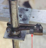
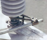
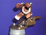
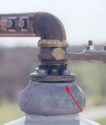
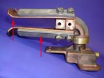
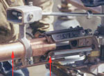
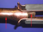
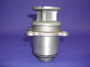 Figure 8
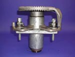 Figure 9