System Details |
|||
|
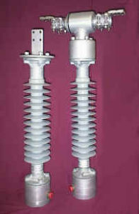
General The SEECO SENSE sensor product consists of four major system components, a Sensor Unit (monitoring insulator), an Output Unit, an Enclosure and Power Source and a Communication Cable. Each sensor unit requires a Communication Cable, however, a single Output Unit may be shared by up to three Sensor Units based on the requirements of a customer’s application. Three distinct sensor unit configurations (figure 1) are available: current-only, type CS; voltage-only, type VS; and combination current and voltage, type CSVS. Type CSVS is identical in external appearance to the current-only sensor and is not represented by a separate picture. All three Sensor Unit configurations share several common design elements. At a high-level, both the type CS and type CSVS sensors have a current sensing mechanism, which the type VS sensor does not require. Similarly, both the VS and CSVS sensor units have a voltage-sensing mechanism, which the type CS sensor does not require. The major system components and their primary sub-component assemblies are described in more detail below. Sensor Unit The Sensor Unit is essentially a monitoring insulator. Depending on the configuration specified, the sensor may include some or all of the following: current sensing coil, voltage sensing rod, silicone polymer station post insulator, two or four hole terminal pads, fiber optic cabling and potting and line and base unit electronic cards.
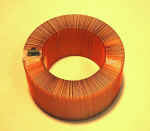
Current Sensing Coil (CS, CSVS) At the high potential side of the unit is a current sensing coil (Rogowski Coil) which is used to sense the line current and generate a safe, low voltage output. The coil (figure 2) eliminates the hazards associated with open secondary windings of conventional CT’s, and the absence of a magnetic core eliminates circuit loading and saturation concerns.
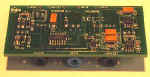
Line Unit Electronic Card (CS, CSVS) The low voltage output is read by the Line Unit Electronic Card (figure 3), which is located adjacent and immediately below the current sensing coil. The card converts the low voltage output from an analog value into a 16 bit digital value. An extremely high sampling rate insures the current value is accurately reproduced for both amplitude and frequency.
Fiber Optic Cabling and Potting (CS, CSVS) The fiber optic cabling and potting (figure 4 front view and 4A back view) provides an insulated pathway for the communication of the current digital signal from the line unit electronic card to the base unit card. A �” diameter hole is centered and bored axially through the insulator core. Three single strand fiber optic cables are run from the top to the bottom of the insulator. An epoxy potting material is used to fill all voids and secure the fibers in place.
Voltage-Sensing Rod/Base Unit Electronic Card (VS, CSVS) At the low potential side of the insulator is a voltage-sensing rod located within the base unit, which transforms the line voltage into a current through induction. The base unit electronic card (figure 3) converts the current generated by the rod to a low voltage analog output. This output is then converted to a 16 bit digital value.
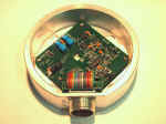
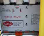
Base Unit Electronic Card (VS, CS, CSVS) The base unit electronic card (figure 5) passes both the voltage digital signal and the current digital signal to the output unit. The card contains a milspec male connector for the communication cable connection. Communication Cable The Communication Cable (figure 6) transfers the output signals from the base unit electronic card to the output unit, and one cable is required per sensor. Since the communication is digital, cable burden is not an issue; maximum cable length is 4,000 feet. The cable has a UV protected black PVC jacket, which is sunlight resistant, impervious to moisture and vapor penetration, and suitable for direct burial in wet or dry locations. Each end of the cable is pre-terminated with a circular MS connector for quick and easy connection to both the Sensor and Output Unit devices. Output Unit (Control Module) The output unit (figure 7) receives and converts the voltage and/or current digital signals into analog signals for use by the customer’s RTU or other related equipment. One output unit supports up to three sensors of the same or different voltage/current configuration. The output unit includes the following sub-components or features: timing and control crystal, digital to analog conversion, status indicators, and an enclosure.
Timing and Control All timing and control signals are generated by a crystal source. This maintains constant timing relationships between voltage and current signals on each phase, and phase to phase.
Digital to Analog Conversion The 16 bit digital voltage and current outputs received from the sensor unit are converted back to analog signals using digital to analog converters. The low level voltage signals are converted into either 120-volt or 10-volt outputs, and each phase voltage output can be field adjusted for scaling. The analog current output range is factory set, and can be provided as either .5 ampere, 1 ampere, or 10-volt full scale. The current outputs provide safe outputs, eliminating the hazards associated with secondary windings.
Status Indicators To facilitate maintenance and trouble-shooting, four status LED’s (figure 8) per phase are provided which indicate the operational condition of all major components of the installed sensor system. An “active” LED is illuminated when all system components are functioning properly or normal state. A failure among any of the system components causes the “active” LED to be turned off. Three LED’s are then used to indicate which major system component is not functioning properly. A control relay is also provided with two sets of contacts (control and status). The control contact can be used to disable a local piece of equipment, such as a motor operator. The status contact provides remote indication of sensor condition. Enclosure/Power Source The Output Unit is typically provided with an enclosure (figure 9). The enclosure is sized to accommodate the output device, terminal blocks for output signal wiring connections, three circular MS connector and power source inputs. A larger enclosure is also available and is sized to accommodate the above material, plus the optional 24 VDC or solar power source, or other customer supplied equipment. The Output Unit will operate with customer supplied 24, 48 and 125 VDC or 120 VAC. An optional SEECO supplied 24 VDC power source complete with batteries, charger and battery testing mechanism can be provided, which requires customer supplied 120 VAC. An optional solar power source is also available. More Information For additional information on SEECO SENSE digital current and voltage sensors, please view the following pages: |
Figure 4 Figure 4A
Figure 5
Figure 6
Figure 7
Figure 9 |
Serving the Electrical Utility
Industry Since 1920